码丁实验室,一站式儿童编程学习产品,寻地方代理合作共赢,微信联系:leon121393608。
产品介绍
点阵共阴共阳问题:
单色点阵LED本无所谓共阳还是共阴,如此命名多半是因为行业习惯造成的。市面上对8*8点阵LED所谓的共阳还是共阴的说法一般是根据点阵第一个引脚的极性所定义的,第一个引脚为阳极则为共阳,反之则为共阴。共阴或者共阳确切的说应该是行共阴或者行共阳。
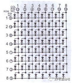
行共阴
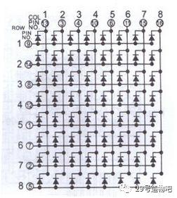
行共阳
管脚定义:
有的点阵后面标有第一脚,但是有的没有标,现在大家默认跟IC的管脚顺序一样,读法是第1脚一般在侧面有字的那一面,字是正向时左边第一脚为1,然后按逆时针排序至16脚,如图示:
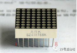
点阵引脚
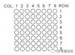
行与列的定义
实验器件
■ 8*8点阵:1 个
■ 面包板:1个
■ 多彩面包板实验跳绳:若干
■ 10K旋钮电位器:2个
实验连线
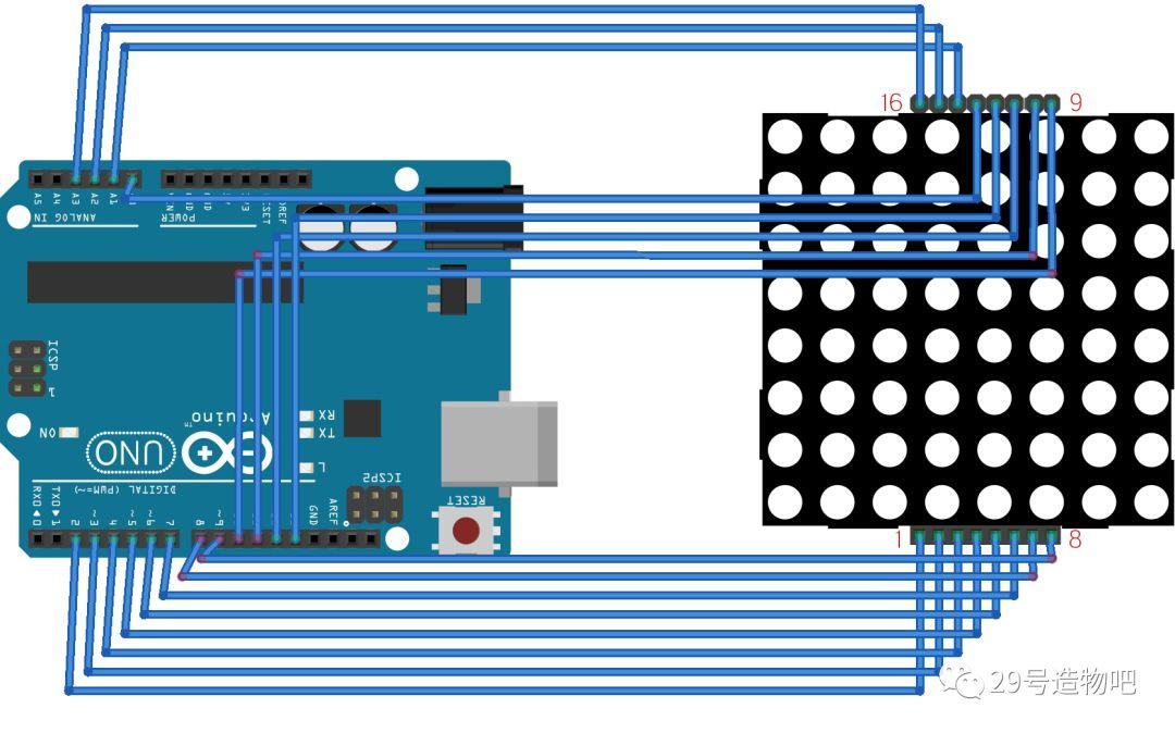
程序代码
// 行引脚对应的数组
const int row[8]={6,11,10,3,17,4,8,9 };
// 列引脚对应的数组
const int col[8]={2,7,19,5,13,18,12,16 };
// 点阵对应的数组
int pixels[8][8];
// 光标位置
int x = A0;
int y = A1;
void setup() {
// 初始化I/O口作为输出
// 循环设置所有需要的引脚
Serial.begin(9600);
for (int thisPin = 0; thisPin < 8; thisPin++) {
// 初始化输出引脚
pinMode(col[thisPin], OUTPUT);
pinMode(row[thisPin], OUTPUT);
// 把对应的引脚引脚置高,确保点亮LED
digitalWrite(col[thisPin], HIGH);
}
// 初始化矩阵像素,8行8列
for (int x = 0; x < 8; x++) {
for (int y = 0; y < 8; y++) {
pixels[x][y] = HIGH;
}
}
}
void loop() {
// 读入模拟输入值
readSensors();
// 绘制屏幕
refreshScreen();
}
void readSensors() {
// 关闭最后1个像素位置
pixels[x][y] = HIGH;
// 读取X和Y的电位器值
x = 7 – map(analogRead(A0), 0, 1023, 0, 7);
y = map(analogRead(A1), 0, 1023, 0, 7);
// 下次刷新屏幕时候拉低电平,以便点亮led
pixels[x][y] = LOW;
}
void refreshScreen() {
// iterate over the rows (anodes):
for (int thisRow = 0; thisRow < 8; thisRow++) {
// take the row pin (anode) high:
digitalWrite(row[thisRow], HIGH);
// iterate over the cols (cathodes):
for (int thisCol = 0; thisCol < 8; thisCol++) {
// get the state of the current pixel;
int thisPixel = pixels[thisRow][thisCol];
// when the row is HIGH and the col is LOW,
// the LED where they meet turns on:
digitalWrite(col[thisCol], thisPixel);
// turn the pixel off:
if (thisPixel == LOW) {
digitalWrite(col[thisCol], HIGH);
}
}
// take the row pin low to turn off the whole row:
digitalWrite(row[thisRow], LOW);
}
}
米思齐代码
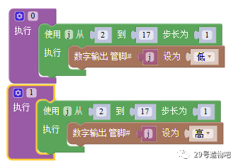
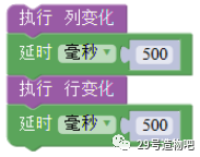
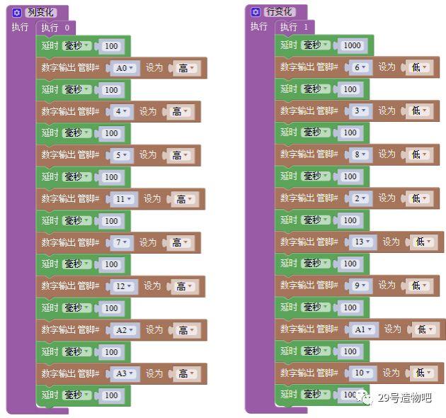
实验结论:
上电点阵上显示一个点,转动行列对应的旋钮电位器,可以移动点阵上点的位置。转动行的旋钮,就可以让点在行上面移动,转动列的旋钮就可以让点在列上移动。
转自公众号:
29号造物吧

