码丁实验室,一站式儿童编程学习产品,寻地方代理合作共赢,微信联系:leon121393608。
W5500以太网控制器芯片外观
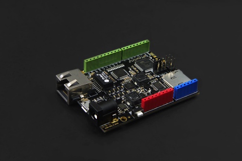
W5500以太网控制器芯片简介
-
W5500 是一款全硬件 TCP/IP 嵌入式以太网控制器,为嵌入式系统提供了更加简易的互联网连接方案。W5500 集成了 TCP/IP 协议栈,10/100M 以太网数据链路层(MAC) 及物理层(PHY)。
-
用户使用单芯片就能够在他们的应用中拓展网络连接。
-
久经市场考验的 WIZnet 全硬件 TCP/IP 协议栈支持 TCP,UDP,IPv4,ICMP,ARP,IGMP 以及 PPPoE 协议。
-
W5500 内嵌 32K 字节片上缓存以供以太网包处理。如果你使用 W5500,你只需要一些简单的Socket编程就能实现以太网应用。这将会比其他嵌入式以太网方案 更加快捷、简便。
-
用户可以同时使用8个硬件Socket独立通讯。
-
W5500 的使用了新的高效 SPI 协议支持 80MHz 速率,从而能够更好的实现高速网络通讯。 为了减少系统能耗,W5500 提供了网络唤醒模式(WOL)及掉电模式供客户选择使用。
W5500 Ethernet with POE Mainboard产品特色
1、以W5500为核心的W5500 Ethernet with POE Mainboard是一款高度集成且符合IEEE 802.3af行业标准POE供电协议的Arduino Leonardo以太网控制板,通过简单的程序移植便可以使之成为一个简单的Web服务器或者通过网络控制可读写数字口和模拟接口等网络应用。
2、产品大小与Leonardo尺寸相等,板载POE供电稳压电路、外接电源稳压电路、SD卡电路以及Leonardo主控单元电路,引出Arduino标准接口。该主控板采用4层布线设计,元件布局紧凑,大大减小了以往Shield+Arduino主板这种可堆叠设计造成的空间浪费问题,小小的尺寸可以为您创造更大的想象空间。
3、为了避免传统低成本DC-DC供电方式在电源变化时系统可靠性较差的缺点,我们不计成本,采用了更加智能和安全的专业PD电源控制集成芯片,使得整个板上系统在许多复杂异常的环境之下均能够稳定可靠的工作。
4、W5500 Ethernet with POE Mainboard兼容POE供电规则中1236信号线供电与4578空闲线供电两种供电方式使得用户不必考虑供电兼容问题。只要是符合IEEE 802.3af行业标准的POE供电设备,你便可以在上面尽情的使用我们的产品。
产品使用注意事项
- W5500 Ethernet with POE Mainboard加入了POE供电电路单元,该高压单元电压高至48V。
- 虽该高压单元电流过低不至于对人体造成伤害,但实际测试时我们发现使用POE供电设备为板子提供电源时,如果手指触摸到主板元件表面有可能造成该高压单元48V电压通过手指导通到低压(5V/3.3V)区域,造成其它功能电路的损坏。
- 由于设计尺寸兼容Leonardo大小(不考虑网口),保护电路元件较多,所以在这样有限的空间内无法再做高低压隔离。
- 为了避免客户直接接触主板元件表面,造成不必要的损坏,我们专门设计了一款亚克力保护盖板,在使用时请勿取下亚克力盖板。
应用领域
- 家庭网络设备:机顶盒、PVR、数字媒体中心
- 串行以太网:门禁系统,LED显示器,无线AP中继等
- 并行以太网:POS机或手持式打印机,复印机
- USB以太网:存储设备,网络打印机
- 保安系统:网络摄像机
- 监控设备
- 嵌入式服务器
技术规格
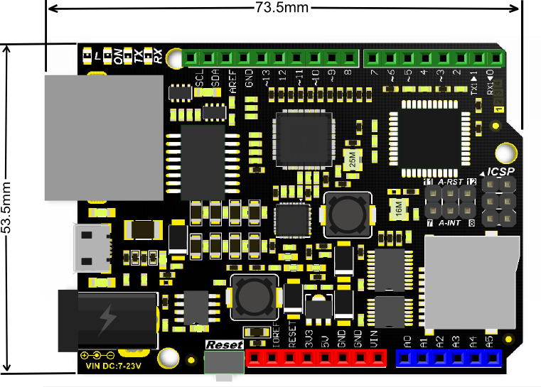
- 微控制器:Atmel Atmega32u4
- 外部输入电压(推荐):7V~23V DC
- 外部输入电压(极限):<23V DC
- POE输入电压:48V AC/DC(本产品为符合802.3af标准的PD设备)
- 数字信号I/O引脚:20(其中6个PWM输出接口)
- 模拟信号输入引脚:6
- I/O接口电流:40 mA
- Flash容量:32 KB (4K用于bootloader)
- SRAM静态存储容量:2KB
- EEPROM存储容量:1KB
- 时钟频率:16MHz
- PHY:WIZnet W5500
- PHY晶振:25MHz
- 尺寸:73.5×53.5x15mm
接口定义
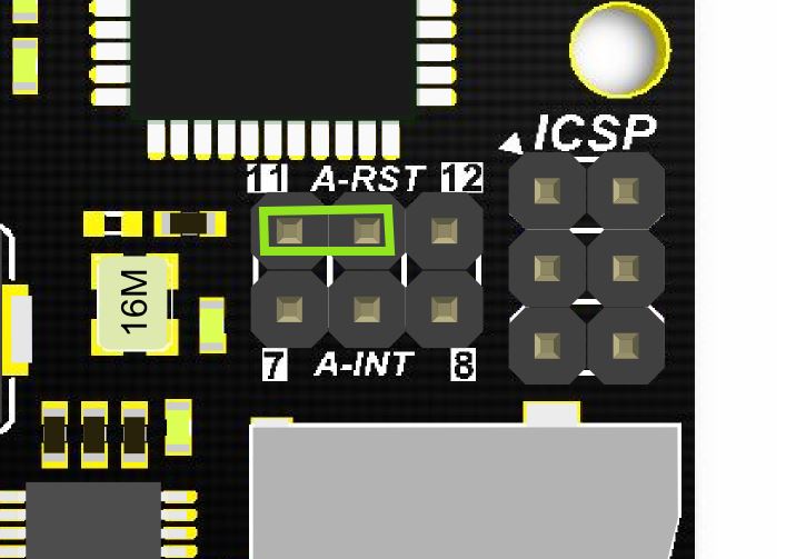
- 板子已额外引出pin7,8,11,12方便连接w5500复位及中断输出引脚。 板子附带两枚跳帽,如果不使用w5500复位及中断输出功能请拔除跳帽,以免影响引脚的正常使用。
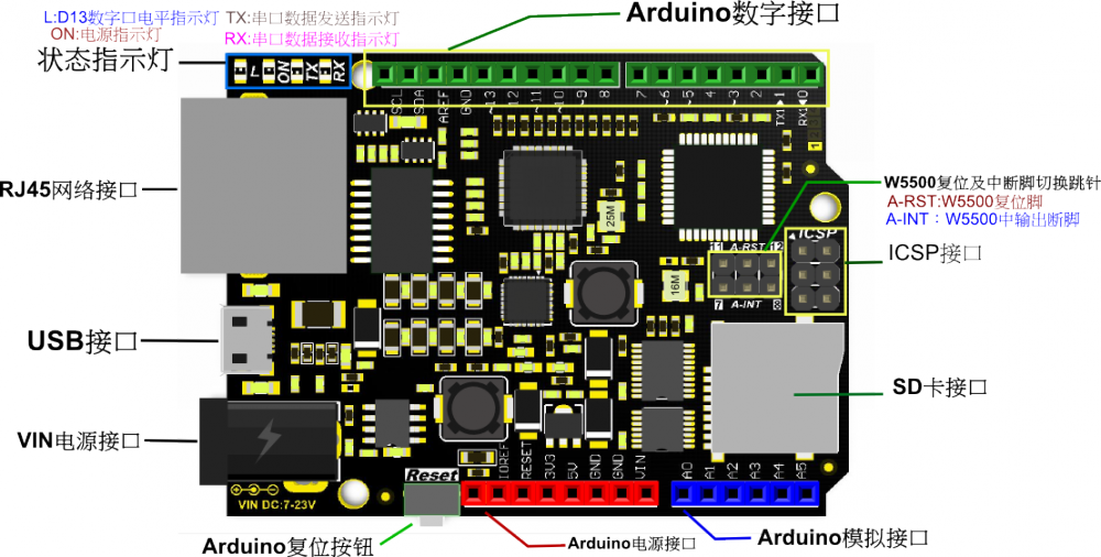
供电方式
- POE供电: IEEE 802.3af标准PSE设备供电
- USB供电: Micro USB供电
- VIN供电: 外接7-23V电源(PCB上有标注)
- 5V引脚供电: 给5V引脚输入5V电源
- 电源会自动选择最高电压输入源作为输入。
应用实例
使用材料:
- 标准POE协议以太网交换机 X1
- W5500 Ethernet with POE Mainboard V1.0 模块 X1
- Micro USB线 X1
- 网线 X1
以下以图文方式介绍板子使用示例:
第一步:将W5500 Ethernet with POE Mainboard V1.0板子上的A-RST脚通过跳线连接到D11脚。
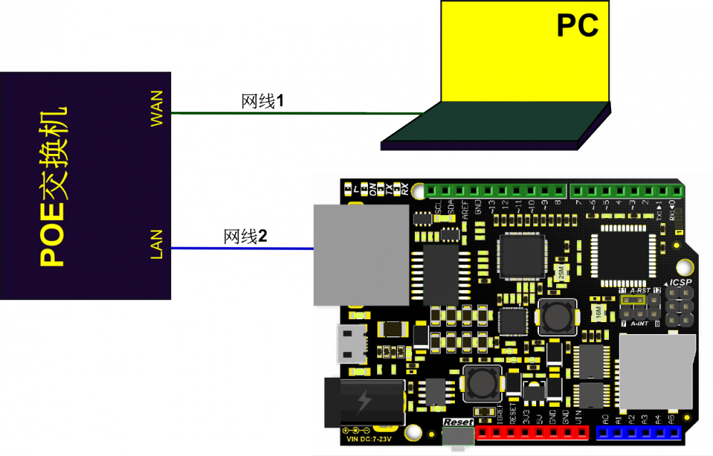
第二步:将W5500 Ethernet with POE Mainboard V1.0板子接上网线插到POE交换机任意LAN端口,也可使用普通交换机、路由设备或直接连接到PC端网口(当使用普通交换机、路由设备或直连PC端网口时需要为模块提供电源)。
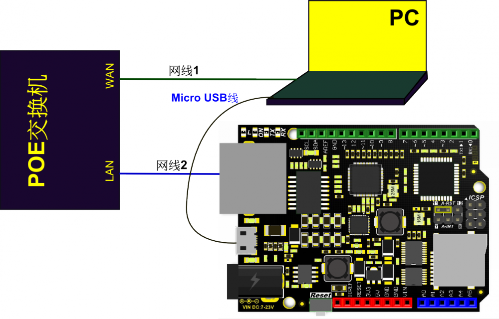
第三步:将Micro USB线插在W5500 Ethernet with POE Mainboard上,另一端接电脑USB口。
第四步:在页面下方“相关下载”栏目按我们给的链接下载WIZnet官方Arduino库,下载后解压压缩包,根据自己使用的IDE版本,选择将解压后Arduino IDE 1.0.x与Arduino IDE 1.5.x两个文件夹之一下的Ethernet文件夹放在Arduino IED的libraries文件内进行覆盖(覆盖原Ethernet库),打开Arduino IDE编译器,在 文件 -> 示例 -> Ethernet 里找到 WebServer 样例并打开。


第五步:在WebServer 样例代码起始处添加复位管脚初始化代码。
/*
  Web Server

 A simple web server that shows the value of the analog input pins.
 using an Arduino Wiznet Ethernet shield.

 Circuit:
 * Ethernet shield attached to pins 10, 11, 12, 13
 * Analog inputs attached to pins A0 through A5 (optional)

 created 18 Dec 2009
 by David A. Mellis
 modified 9 Apr 2012
 by Tom Igoe

 */

#include <SPI.h>
#include <Ethernet.h>

#define SS     10U    //W5500 CS
#define RST    11U    //W5500 RST

// Enter a MAC address and IP address for your controller below.
// The IP address will be dependent on your local network:
byte mac[] = {
  0xDE, 0xAD, 0xBE, 0xEF, 0xFE, 0xED
};
IPAddress ip(192, 168, 1, 177);

// Initialize the Ethernet server library
// with the IP address and port you want to use
// (port 80 is default for HTTP):
EthernetServer server(80);

void setup() {

  pinMode(SS, OUTPUT);
  pinMode(RST, OUTPUT);

  digitalWrite(SS, LOW);

  digitalWrite(RST,HIGH);  //Reset this module
  delay(200);
    digitalWrite(RST,LOW);
  delay(200);
  digitalWrite(RST,HIGH);
 delay(200);
  // Open serial communications and wait for port to open:
  //Serial.begin(9600);
  //while (!Serial) {
  //  ; // wait for serial port to connect. Needed for Leonardo only
  //}


  // start the Ethernet connection and the server:
  Ethernet.begin(mac, ip);
  server.begin();
  //Serial.print("server is at ");
  //Serial.println(Ethernet.localIP());
}


void loop() {
  // listen for incoming clients
  EthernetClient client = server.available();
  if (client) {
    //Serial.println("new client");
    // an http request ends with a blank line
    boolean currentLineIsBlank = true;
    while (client.connected()) {
      if (client.available()) {
        char c = client.read();
        Serial.write(c);
        // if you've gotten to the end of the line (received a newline
        // character) and the line is blank, the http request has ended,
        // so you can send a reply
        if (c == 'n' && currentLineIsBlank) {
          // send a standard http response header
          client.println("HTTP/1.1 200 OK");
          client.println("Content-Type: text/html");
          client.println("Connection: close");  // the connection will be closed after completion of the response
          client.println("Refresh: 5");  // refresh the page automatically every 5 sec
          client.println();
          client.println("<!DOCTYPE HTML>");
          client.println("<html>");
          // output the value of each analog input pin
          for (int analogChannel = 0; analogChannel < 6; analogChannel++) {
            int sensorReading = analogRead(analogChannel);
            client.print("analog input ");
            client.print(analogChannel);
            client.print(" is ");
            client.print(sensorReading);
            client.println("<br />");
          }
          client.println("</html>");
          break;
        }
        if (c == 'n') {
          // you're starting a new line
          currentLineIsBlank = true;
        }
        else if (c != 'r') {
          // you've gotten a character on the current line
          currentLineIsBlank = false;
        }
      }
    }
    // give the web browser time to receive the data
    delay(1);
    // close the connection:
    client.stop();
    //Serial.println("client disconnected");
  }
}
第六步:编译并烧写。烧录完毕后可以拔掉Micro USB线(若使用普通交换机或路由设备请不要拔掉Micro USB线除非有其它外接电源的情况下),打开浏览器->输入IP地址->回车打开网页。
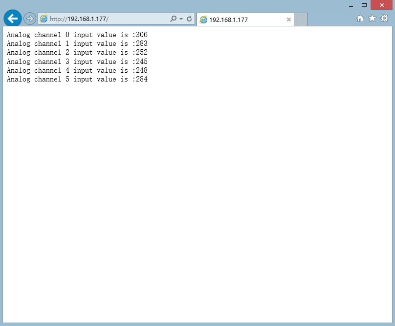
在页面中我们可以看到板子6路模拟口输入值在网页上按5S/次的频率自动刷新显示,此时说明我们创造的一个小型Web Server已经正常工作了。
异常情况解决办法:
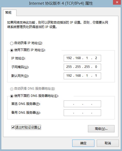
对于计算机浏览器出现“网页无法加载”问题的小伙伴儿先不要着急,请按照如下步骤配置你的网络适配器:
1、打开控制面板–>网络和 Internet–>网络和共享中心–>更改适配器设置
2、找到你连接模块的网络–>右键–>属性–>在网络选项卡中找到“Internet协议版本4(TCP/IPv4)"并双击进入属性设置
3、输入下图所示参数并点击确定。在此之后再按照上面示例中第六步操作就行了….
接下来……. 小伙伴儿们,充分发挥你们的想象吧…..
POE供电简介参考度娘百科
相关下载
原理图下载
W5500数据手册
官方Arduino库下载链接

